What are the test points for a building ball valve?
Building valves are an essential element for all fluid transport networks. The ball valve, which is widely used by construction professionals, is used to stop the flow of a fluid in a pipe. The reliability of a valve is essential to avoid disasters. Tests are carried out on valves to ensure that they comply with the requirements and performances required in terms of tightness, resistance or endurance. Here is a closer look at the ball valve, its characteristics, its use and the main tests carried out on test benches.
SOMMAIRE
What is the purpose of a ball valve for the building industry ?
Definition, principle and characteristics
The ball valve, or ball plug, is an industrial valve designed Ball valveto regulate the flow of a fluid through a pipeline.
The most common ball valve is the two-way valve, corresponding to the positions open (for fluid flow), and closed (to shut off fluid supply). Used primarily as an on-off shut-off valve, the ball valve can be used as a flow control valve if fitted with a suitable control gate.
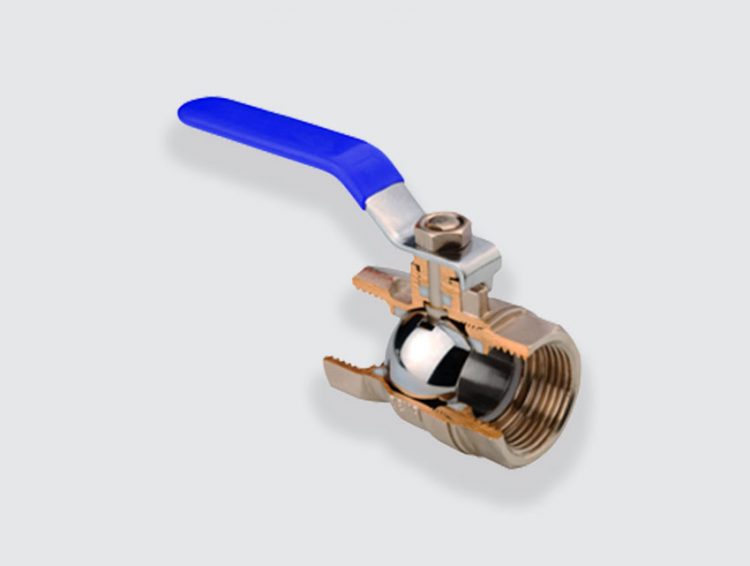
The ball valve consists of a ball with a hole in it, the ball. To block or allow the flow of fluid in the ring, the ball rotates 90° on an axis. Sealing is provided by the flanks of the ball in the valve body. The valve can be full bore, which means that the valve opening is the same size as the inside of the pipe.
Ball valves are made of materials that can withstand corrosion and high stresses. Stainless steel, brass, stainless steel, bronze, the materials differ depending on the type of fluid flowing through the pipe. For heating and water supply, a brass ball valve is mainly used.
The ball valve does not allow for precise regulation but it does allow for quick and effortless operation. Simply rotate the ball a quarter turn to fully open or close the valve. Ball valves are generally quarter-turn valves operated by handle or lever rather than by handwheel.
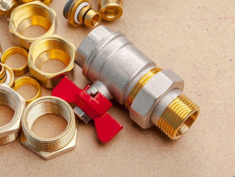
The position of the ball valve handle indicates the degree of opening or closing of the internal ball. When the ball is open, allowing fluid to flow, the handle is located in the extension of the tube. When the ball is closed and the fluid is stopped, the handle is perpendicular to the pipe.
Although most ball valves are manually operated, they can also be motorised for remote control or robotic operation.
When should a ball valve be used ?
The ball valve is widely used in the construction industry, in fluid transport networks in plumbing and HVAC.
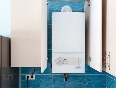
t is used, for example, for the installation and assembly of water pipes, the installation and assembly of a boiler, or for the installation of a radiator or heating system.
Ball valves are used in industrial applications in various sectors. Chemicals, foodstuffs, mechanical engineering, industry, these valves can be used in installations where water, oil or gas is flowing.. They also play an important role in energy and environmental engineering.
Do you have a project ? Contact our test bench experts
What are the test points of a ball valve?
Tests according to the European standard
As with sanitary fittings, building industry fittings are regulated by standards and certifications that attest to the quality and reliability of a product.
The European standard NF EN 13828 applies mainly to ball valves. It specifies material and design requirements for valves, mechanical, hydraulic and acoustic requirements, and the test methods used to verify these requirements.
The main types of tests
To meet the hydraulic requirements, the tests performed on the valves are as follows:
- Leak test: The leak test is used to identify leaks in a valve. To comply with the standard, the valve must withstand a pressure of 16 bar upstream and 4 bar downstream. There must be no leakage from the valve.
- Pressure resistance test: The pressure test verifies the mechanical strength of the valve body. The valve must be able to withstand a pressure of 25 bar without deforming. . During a pressure test, the valves must not show any visually detectable leakage.
- Mechanical strength test: The mechanical strength test is used to test the bending and twisting of the valve. It is used to check the resistance to various mechanical stresses (e.g. operating torque)
- Endurance test: The endurance test is used to meet the requirements of the operating time and to check the reliability of the valve against wear. The principle of the endurance test is to cyclically reproduce the mechanical stresses experienced (opening/closing) during the entire operating time of the valve. The water flowing through the valve reaches a temperature of 65° and a pressure of 3 bar.
Tests in accordance with the NF mark
The NF079 mark – Control and safety valves is based on the NF EN 13828 standard and raises the level of requirements of the European normative framework. The checks carried out for the issue of the NF mark confirm the quality and performance of the valves in terms of :
- resistance to pressure,
- resistance to pressure cycles,
- resistance to temperature cycles,
- resistance to operating cycles,
- resistance to corrosion.
Certified performance
- Hydraulic resistance of the operating shaft: The test verifies that there is no ejection of the pin when the valve is under pressure (6x nominal pressure, 160 bar max).
- Mechanical tensile strength: The tensile test verifies the degree of resistance to breakage of a material. The tensile strength is 11 to 25 kN depending on the size of the valve.
- Alternating pressure resistance: The test determines the resistance to alternating pressure stresses. Cycling varies from 0.5 to 1 Hz between 2 pressure levels.
- Actuating torque test: The test is comparable to the one carried out under EN 13828, with different torque values.
- Mechanical strength of the stops and spindle: The test is comparable to that carried out in the framework of EN 13828, with different torque values.
- Leakage test: The test is comparable to that carried out in the framework of EN 13828.
- Hydraulic resistance: The test is comparable to that carried out in the framework of the standard, with a test pressure of 2.5x nominal pressure..
- Endurance in 3 Phases: The test is performed in 3 phases:
– Phase 1: fluid circulation at 110°C for 1 hour
– Phase 2: 50% of the cycles with a fluid at 90°C
– Phase 3: 50% of the cycles with a fluid at -5°C
Shut-off and draw-off valves, globe valves, butterfly valves, valve extensions, building valves are tested in the laboratory on test benches.
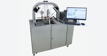
To control and evaluate the performance of building valves, the CSTB uses LF Technologies hydraulic test benches.
The LF Technologies test benches guarantee compliance with the standards and certifications applicable to control and safety valves. They provide the assurance that a product complies with the quality and safety requirements of the regulations.
Discover other articles and tips

What methods are used to test pipes in the building industry?
Who are the test benchusers?
What are the most important tests on sanitary hoses ?
